CSCI 343 April 3: MIPS Pipelining, Parallelism, and Hazards
Overview
This lecture focused on instruction-level parallelism via pipelining in MIPS architecture, a technique designed to improve performance by increasing instruction throughput. Key topics included:
- The five-stage instruction cycle
- Parallelism through pipelining
- Hazards in pipelining: structural, data, and control
- Techniques to handle data hazards: stalling, forwarding, and delayed branching
- Why MIPS is ideal for pipelining
- Pipeline timing and speedup
- Hardware support for pipeline optimization
- Real-world analogies and examples
Five-Stage Instruction Cycle in MIPS
Each MIPS instruction may go through the following five stages:
- Instruction Fetch (IF) - Access instruction memory
- Instruction Decode (ID) - Decode and read register operands
- Execute (EX) - Perform ALU operations
- Memory Access (MEM) - Read/write data memory (only for load/store)
- Write Back (WB) - Write result to register file
Not every instruction uses every stage actively, but all must pass through each stage in a pipelined design.
Some instructions like R-format skip MEM, and store instructions skip WB. Branch instructions may skip both MEM and WB. However, all must move through all stages to maintain pipeline structure and timing.
Key Idea
Each stage uses a different hardware component (e.g., instruction memory, register file, ALU, data memory), allowing multiple instructions to proceed in parallel without interference.
Pipelining Basics
Pipelining increases throughput by overlapping stages of multiple instructions. Each pipeline stage operates on a different instruction during the same clock cycle.
Analogy: Doing Laundry
- Tasks: wash → dry → fold → store
- Instead of waiting for one load to finish before starting another, each stage is continuously active on a different load
- Pipeline performs like a laundry assembly line: once the line is full, each step outputs a finished product every cycle
Requirements for Pipelining:
- No two instructions can use the same hardware unit in the same clock cycle
- All instructions must progress through the pipeline stages in order
Advantages of Pipelining
To illustrate how pipelining reduces total clock cycles, refer to the diagram linked below:
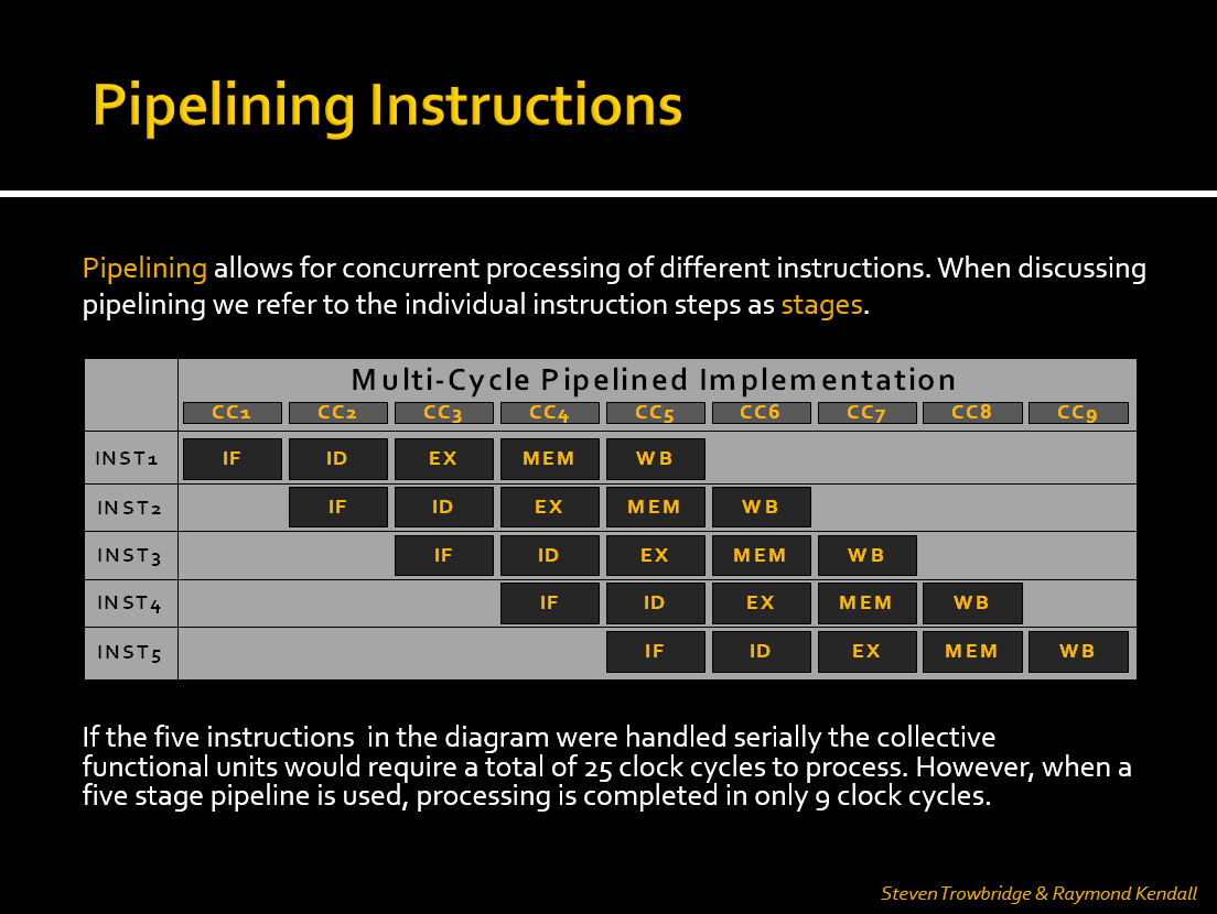
- In a non-pipelined (serial) approach, each instruction must complete before the next begins. With five instructions and five stages, this would take 25 cycles.
- In a pipelined CPU, overlapping stages allows all five instructions to complete in just 9 clock cycles.
- Throughput Improvement: Completes more instructions per unit time (not faster individual instructions)
- Efficiency: Better hardware utilization compared to single-cycle CPUs
- Example:
- Single-cycle: 5 instructions × 800ps = 4000ps
- Pipelined: 9 cycles × 200ps = 1800ps (more than 2× improvement)
Pipeline Timing & Speedup
- Pipeline clock cycle is set to the slowest stage (typically MEM or EX)
- With each instruction taking 5 stages, a pipeline allows completion of one instruction per cycle after the pipeline is full
Pipeline Time = (n + k - 1) × t
where:
    n = number of instructions
    k = number of stages (5 for MIPS)
    t = clock cycle time (determined by slowest stage)
This formula calculates the total time required to execute n instructions through a pipeline with k stages and clock cycle time t. It reflects the idea that the first instruction takes k cycles to complete, and each additional instruction completes in one additional cycle.
In the Pipeline visualization above:
- We can see how the pipeline fills up over the first few cycles.
- Once full, each new instruction completes every cycle.
-
With 5 instructions and a 5-stage pipeline, the total time is 9 cycles, coinciding with the formula stated above:
(5 + 5 - 1) × t = 9 × t. - Ideal Speedup ≈ number of stages (5), but actual speedup is less due to hazards and pipeline filling/draining overhead
MIPS Design and Pipelining
MIPS architecture is designed with pipelining in mind. Features include:
- Fixed-length instructions (32 bits) simplify fetching and decoding
- Regular instruction formats share field locations (opcode, rs, rt, etc.)
- Load/store architecture restricts memory access to only two instructions, simplifying memory stage handling
- Aligned memory accesses ensure word-based access boundaries
These choices allow each pipeline stage to be predictable and efficient, with less complex control logic.
Pipeline Hazards
Pipeline hazards are issues that prevent the next instruction from executing during its designated clock cycle.
1. Structural Hazards
- Cause: Two instructions attempt to use the same hardware component simultaneously
- Solution: MIPS avoids these by design (e.g., separate instruction/data memory)
2. Data Hazards
- Cause: Dependency between instructions (e.g., one instruction needs a result from another still in progress)
-
Types:
-
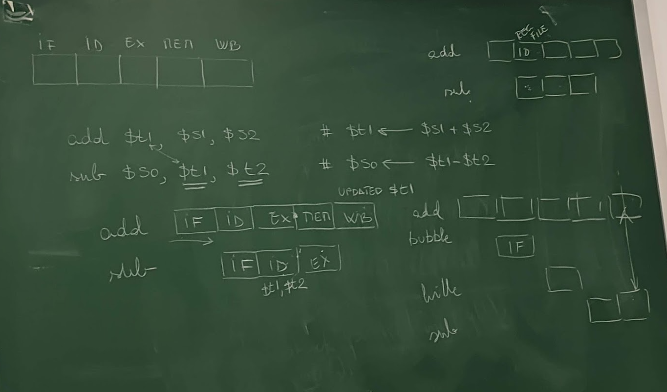
RAW (Read-After-Write): Most common
e.g.
add $t1, $s1, $s2
sub $s0, $t1, $t2  # Depends on result of add
-
Solutions:
-
Stalling (Bubbles)
- Pipeline inserts NOPs to delay dependent instruction
- Implemented using a hazard detection unit, which sets control signals to zero to pause progress
-
Forwarding (Bypassing)
- Directly route results from EX/MEM or MEM/WB stages to dependent instructions
- Done using a forwarding unit and multiplexers
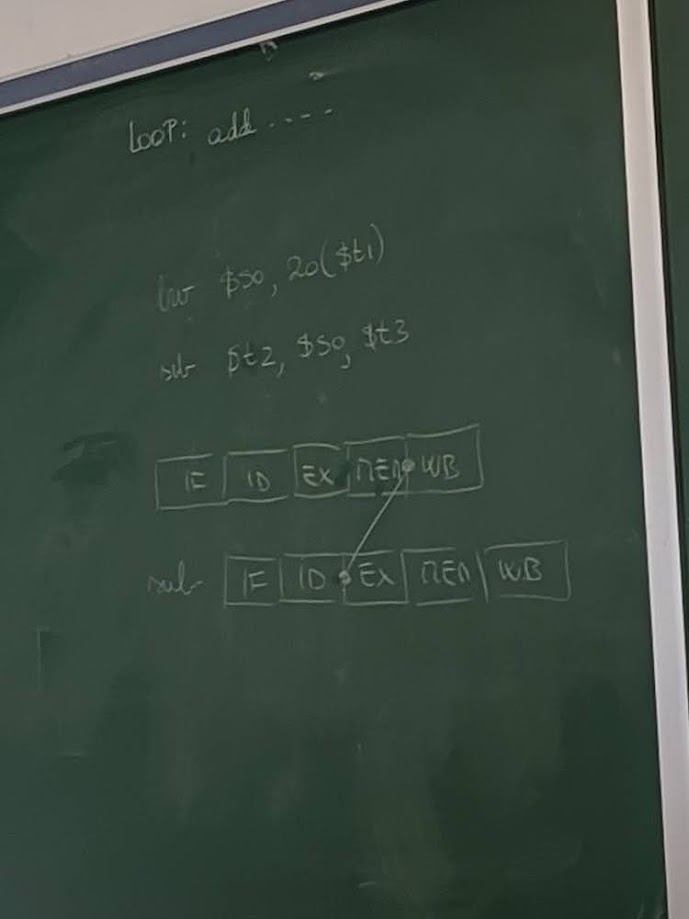
Load-Use Hazard
- Special Case: Load data isn’t available until MEM stage, requiring a stall + forward combo.
lw $s0, 20($t1)
sub $t2, $s0, $t3  # Requires stall before forwarding
3. Control Hazards (Branch Hazards)
- Cause: Branches alter instruction flow, but the next instruction is fetched before branch resolution
Solutions:
- Flush: Discard wrong instruction if prediction was incorrect
- Branch prediction: Guess the likely path; dynamic algorithms can improve accuracy
- MIPS Approach - Delayed Branching:
- Always fetch the next instruction after the branch
- The next instruction (delay slot) is always executed, regardless of branch result
- Compiler reorders code to place useful instructions in the delay slot
- Static prediction: MIPS assumes branches are not taken
Pipeline Registers & Forwarding Unit
Pipeline registers isolate each stage and store information needed by subsequent stages. This supports overlapping execution and forwarding.
Typical Inter-Stage Registers:
- IF/ID: Holds fetched instruction and PC+4
- ID/EX: Holds control signals, register values, and sign-extended immediate
- EX/MEM: Holds ALU result, control signals, and destination register
- MEM/WB: Holds data from memory or ALU result to write back
Forwarding Unit
- Contains multiplexers that bypass pipeline registers to feed results directly to dependent stages
- Used to resolve most RAW data hazards without stalling
Performance Comparison
| Model | Instructions | Clock Cycles | Clock Time | Total Time |
|---|---|---|---|---|
| Single-cycle CPU | 5 | 5 × 800 ps | 800 ps | 4000 ps |
| Pipelined CPU | 5 | 9 cycles | 200 ps | 1800 ps |
- The pipeline requires extra cycles at the beginning and end (startup + wind-down)
- With large programs (e.g., 10,000+ instructions), pipeline stays fully utilized, and overhead becomes negligible
- Real performance boost comes from throughput, not faster individual instruction execution
Example Problems
Data Hazard with Forwarding
add $s0, $s1, $s2
sub $t0, $s0, $s3  # Forward $s0 from EX to EX
Load-Use Hazard
lw $s0, 0($t0)
add $t1, $s0, $t2  # Requires 1 stall cycle + forwarding
Summary of Hardware Support for Pipelining
- Forwarding Unit: Enables bypassing of values to avoid unnecessary stalls
- Hazard Detection Unit: Inserts NOPs (bubbles) when data hazards are unavoidable
- Control Unit: Modified to manage stalls, flushing, and branch decisions
- Pipeline Registers: Store and isolate stage-specific values to support concurrent processing
Exam Notes
- Understand the function of each pipeline stage and what hardware it uses
- Be able to draw a pipeline execution chart for a sequence of instructions
- Identify and explain the type of hazards between instructions
- Demonstrate both stalling and forwarding solutions for data hazards
- Know how MIPS design simplifies pipelining and supports delayed branching
- Calculate clock cycles and performance gains for pipelined vs. single-cycle execution
- Explain why load-use hazards require stalling even with forwarding
Suggested Reading
- Hennessy & Patterson textbook chapters on pipelining, data hazards, and control hazards
- PowerPoint slides posted on Brightspace for pipeline and hazard diagrams
- Study older student presentations (e.g., by Steven Trowbridge & Raymond Kendall)
- Practice interpreting pipeline diagrams like the one above